Step 4: Propeller Selection
Now that we have quickly covered momentum theory and dug out the necessary equation relating power and thrust, we will move towards propeller selection. You can fill in the amount of mass in order to eliminate thrust as a variable leaving power alone to solve for. But knowing the power necessary to produce thrust is not enough. You also need to know the rotational speed required of a propeller to produce that power. And the final step will then be to coordinate that propeller with an appropriate motor.
This article will cover how to derive propeller speeds and figure of merit, the two essential variables in selecting your propeller.
A quick side-note: If you are mathematically inclined, you may find value in researching Blade Element Theory for propeller optimiztion. However, heed this warning per an article we found from Georgia Tech which you can read here. "The combined blade element - momentum theory is an improvement over previous theories, al though it has the ad hoc assumption that each annulus behaves independently of the neighbor rings. It does not model two sources of losses, that must be addressed before it may be used in practical calculations." It goes on to describe those two types of losses - "Tip Loss" and "Swirl" - and seems to also say that after accounting for those two losses the model is still lacking in its ability to match empirical data. Currently we see the best value in using Momentum Theory with empirical propeller data rather than combining it with Blade Element Theory AND additional work to counteract the inherent inaccuracy of a simple combination of the two theories.
Part 1: Benchmarking
Let's start with propeller speed. What we need now is an equation to relate propeller rotational speed to power. And it is exceptionally important to say now that the equations we've found relate rotational speed to lifting power specifically. What we will do first is develop a method for you to derive an approximate rotational speed as a function of mechanical motor shafter power. We've already derived an equation for lifting power as a function of static thrust. This actually really does get quite tricky and it's easiest to rely on some empirically derived constants with their appropriate equation.
In general the equation for mechanical power as a function of rotational speed is as follows:
Equation 7: P = C*n3 where P is mechanical power from a motor driving a propeller at some rotational speed n rotationas per minute divided by 1000 and C is some constant related to a specific propeller
Empirical data does suggest that a constant exponent of 3 is not necessarily the case which leads to a new equation as follows:
Equation 8: P = C1*nC2 where C1 and C2 are constants related to a specific propeller and C2 being a number close to 3 (P and n are unchanged)
Remember to always be extremely careful to identify the appropriate units with any equation you use. If you don't use the correct units the results won't make sense. Note here that if you want to solve for a rotational speed of 10,000 rpm you would input the number 10 into the equations above.
Hyperion put together some good information here. And they recorded a wealth of data here.
The equation for use with these constants defined by Hyperion is
Equation 9: P = Prop Constant*nPower Factor where C1 from Equation 8 is defined as the variable "Prop Constant" and C2 from Equation 8 is defined as "Power Factor".
Now we are very close to being able to solve for rotation speed but we are pretty stuck. We have an equation relating rotational speed to mechanical motor shaft power and equation relation thrust to lifting power. In order to solve for the rotational speed of a propeller to lift a quadcopter of a given weight we need to know the figure of merit of the propeller to relate the two different stages of power. For a very rough estimate you can assume a figure of merit of 50% but given the right data for a given propeller we can do much better that. At this point you should have a decent educated guess at least at how this stuff works and you have a benchmark against which to test some power data still to come.
You should go ahead and put all of this information together in a spreadsheet. Here is example of a sheet for thet APC SlowFly series of propellers.

Part 2: Figure of Merit
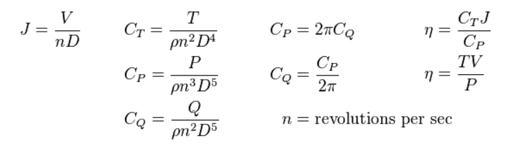
However, for a serious quadcopter design, you really don't want to use approximations like the one above. It's okay to fill in 50% to get an idea of what to expect, but we will now cover how to actually calculate the figure of merit of a propeller. Here are some standard equations using a variety of propeller coefficients.
 Source: UIUC
(For more information feel free to take a look at McCormick, B.W., "Aerodynamics, Aeronautics, and Flight Mechanics," Wiley, Second Edition, 1995.)
Source: UIUC
(For more information feel free to take a look at McCormick, B.W., "Aerodynamics, Aeronautics, and Flight Mechanics," Wiley, Second Edition, 1995.)
Don't get too bent of shape yet. We will make this process relatively simple.
Here are what those variables are:
J - Advance ratio (A fancy term that accounts for if a propeller is moving relative to a coordinate plane - not to be confused with the velocity of the air passing through the prop area even at a hover)
Cp - Coefficient of power
Ct - Coefficient of thrust
Cq - We won't concern ourselves with it here. But feel free to look into it.
Regular n - rotational speed
Fancy n - Figure of merit
ρ - density of air
D - Propeller diameter
V - Local air velocity in streamtube
T - Thrust
P - Mechanical power supplied to turn propeller
For a great place to start working with these equations and seeing them in action, go visit the great site put together by the UIUC Department of Aerospace Engineering that I sourced for the equations here.
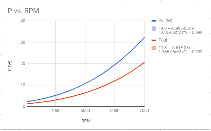
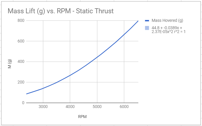
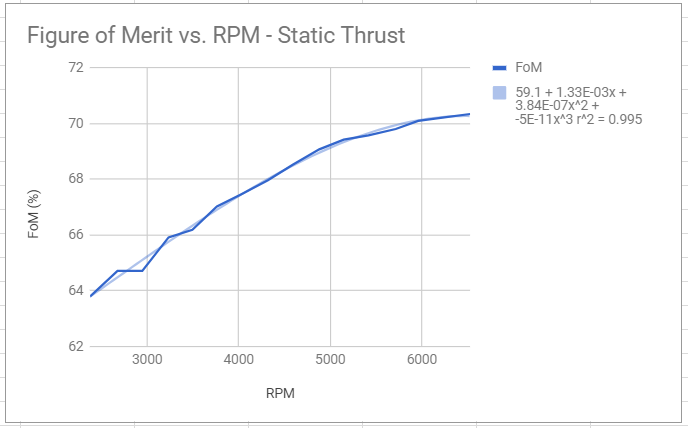
Here we will concern ourselves only with the static data. We won't concern ourselves with graphs where the horizontal axis is advance ratio because the advance ratio is unchanging at a hover. It is time for another... you guessed it... spreadsheet. We advise assigning a dedicated sheet for each propeller. Now copy over the static test data for Ct, Cp and RPM into a column each. UIUC assigns for Cto and Cpo respectively for the static case. Finally, assign output columns with the formulas for Ct and Cp above solved for thrust (T) and power (P). Also assign a column and calculate the corresponding mass hovered by dividing thrust by g for a more relateable quantity of lift. Next assign an output column using our prior formulation for power. Use the calculated thrust column as an input for this column. Remember that lifting power is equal to the product of lifting thrust and air velocity (TV). We now have both pieces for the figure of merit calculation. Simply divide TV by P and multiply by 100 to convert the fraction to a percentage. See below for an example!
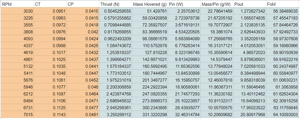
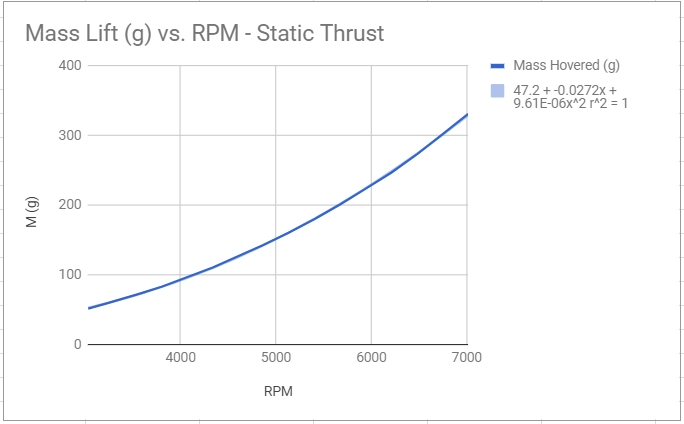
Next, you can build some graphs as a function of rpm.
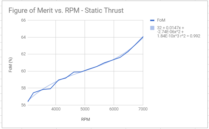
Now you can go back to your original spreadsheet and creat a column with rpm as an input and calculate the figure of merit with a trendline fit as you can see on the FoM graph above. This is the missing piece we discussed above and completes your rpm and power calcuations. At this point you could move on to matching a motor based by matching its power and rotational speed to the mechanical power and rpm necessary to hover your quadcopter of a given mass... assuming your given mass is accounted for by the available data. In the example above this data isn't very helpful for a quadcopter with a mass of 2kg (500g of lift required per motor).
At this point in the design arises the need for more multirotor specific data with larger ranges of speed and thrust. Maybe a decade ago, probably basically every propeller you saw at a hobby store was for a plane - not a multirotor UAV. A plane doesn't need to produce as much thrust with it's propeller to fly. This is readily reasoned by considering its inertia. A plane's inertia contributes to its lift in that the mass of the plane moving forward through the air is the mass concerned in inertia and producing lift across the wings. However in a quadcopter (we have to skip to rotational inertia here rather than translational) the inertia for lift is governed in that the propeller must continue turning to produce lift, and at a much higher rate of speed than that of a large wing moving throught the air for a plane of the same weight. Remember that the larger the airfoil the lower the air speed needs to be. A couple further things to note!
- It doesn't make sense that the FoM does not show much sign of leveling off and eventually dropping as rotational speed increases. One would at least guess that a peak should occur. This suggests the dataset to be too small.
- We already mentioned that the data we just looked at wouldn't help us with a quadcopter heaving than about 1.2kg. At this point one would at least guess that we may want to spin the prop faster to lift the a heavier quad. But then we must stop to consider what the maximum allowable rotational speed of a propeller is - especially one that is labled SF for "Slow Fly" like those common APC propellers are. So the bottom line is that the data here, though fantastic, is lacking. We need more quadcopter specific data!
Part 3: Final Selection of Multirotor-specific Propellers
And we found that data at APC's website here! We found propellers designed specifically for quadcopters. We found extensive data to perform the necessary calculations for our quadcopter design. And we found maximum rated rotational speeds for APC's propellers. Now let's observe the answers to the concerns pointed out above.
Start by looking at the propeller RPM limits here. For the SF propellers the RPM limit is equal to 65,000 divided by the propeller diameter in inches. That means that maximum rotational speed for the propeller in our example above is just 8,125RPM! (Kudos to UIUC for not exceeding the limit of this propeller in the data they gave!) So this propeller can only lift a quadcopter slightly heavier than 1.2kg. If you are wanting to build a videography setup then this propeller is not right for you. Just to nail this point down let's look at a couple of graphs for a 10 inch diamater SF propellers. And note that the max rotational speed for this propeller is 6,500 RPM.
Here the data is looking much better for a larger quadcopter without exceeding the ratings.
But we still need to address the FoM. We see a suggested peak, perhaps just a leveling off, of the FoM. But we actually don't need to concern ourselves with too much because to push higher RPM's is to exceed the rotational speed rating. But what if we wanted still more lifting capacity with the propeller and the figure of merit graphing to accompany it? Or what if we want to keep the UAV so small that 8 inch propellers are the maximum? And are these really just plane propellers getting thrown on a multirotor?
Well APC actually has a line of multirotor (MR) propellers! Let's first look at the RPM limits of these propellers. To get the limit of the propeller it says to divide 105,000 by the diameter of the propeller in inches. Notice that these propellers can spin a whopping 62% faster than the SF series! This means greater lifting capacity for smaller propellers! This the series of propellers we want to select a propeller set from.
Now let's take a look at the performance data here. What we are basically going to do is step through the same process of design as before with the data given here. You should end up with a table that looks something like the table below (8x45MR propeller).
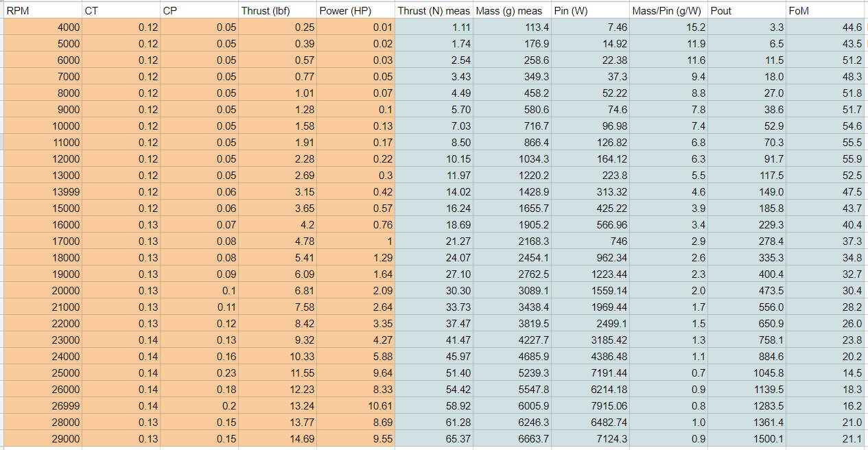
Observe how this 8 inch propeller can lift significantly more mass than the SF 8 inch propeller we showed above. And last but not least, let's look below at the corresponding FoM graph.
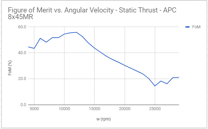
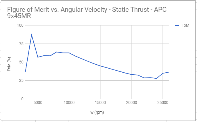
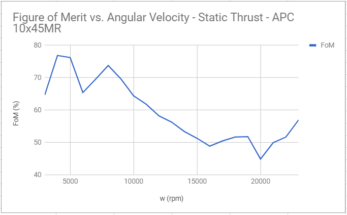
And look at that. We see that the FoM actually has an ideal RPM on either side of which the FoM decreases. Given the range of FoM values possible, it is clearly important to design for as a high an FoM as possible! Let's look at the FoM graphs of some other APC MR propellers for comparison.
Conclusion
In conclusion, the following basic steps should be followed in selecting a propeller up to this point.
- Define a preliminary mass for your quadcopter.
- Set up an equation to solve for rotational speed necessary to hover that mass for multiple propellers based on Momentum Theory as detailed previously.
- Set up graphs including rotational speed, thrust, mechanical power, lifting power, and FoM for different propellers based on empirical data.
- Find the rotational speed necessary to hover that mass based on this empirical data and then compare against your initial calculations as a check.
- Compare propellers to find the one which will hover your quadcopter at the highest FoM value.
Once you have followed these steps, you will have a propeller selected with a corresponding RPM necesesary to hover and power from motor (to the propeller) necessary to hover. This establishes what we define as a "motor operating point" and brings us to our next article: Motor Selection.