Step 7: Electronics Selection
The next step is to nail down the electronics for the quadcopter. Some items to consider are electronic speed controllers (ESC), power distribution board (PDB), power monitoring unit (PMU), flight controller, receiver, transmitter, and LED indicator(s). The difficulty in the design process is the interdependence of the various components. Changes to the motor and battery selections can drastically affect the electronics selections.
Part 1: Electronic Speed Controller
The motors themselves are purely a passive element. Extra circuitry is needed to control the current through the motors and the corresponding torque. Electronic speed controllers are essentially smart transistor switches. They have microcontrollers which receive a control signal from some external source such as a flight controller or a wireless receiver. Based upone the input signal, the microcontroller turns larger transistors on and off. These transistors are connected to the main power supply. When turned on, current flows through the motor. The microcontroller plays a critical role in not just the interpretation of the input signal but also in the closed loop control of the motor. In the case of brushless motors, it can detect the rotor position. This is important for two reasons. First, it determines the sequence in which the stators need to be energized. Second, it allows the microcontroller to measure the speed of the motor. By taking the latter into account, it can change the frequency of the current pulses to the motor in order to meet the specified throttle setting. More advanced ESCs can even have regenerative braking where a speed reduction charges the battery.
ESCs primarily have two specifications that are critical to the design process. The first is current capacity. Larger motors require higher levels of current. The ESC has to be able to handle these amounts with larger transistors and better cooling. There are two ratings: continuous current and burst current. Continuous current is the main specification with the burst current being a margin of safety. It is acceptable to have the continuous current rating match the motor rating. However, having a higher ESC rating gives an added margin of safety and durability. It is important to emphasize that the ESC current rating does not determine the current draw. The current consumption is ultimately set by the motor.
The second ESC parameter is the input signal. Most ESCs accept some form of pulse width modulation, and the most common setting is to have a 490Hz update rate with a 1ms-2ms width range such that a 1ms pulse represents 0% throttle and 2ms is 100%.
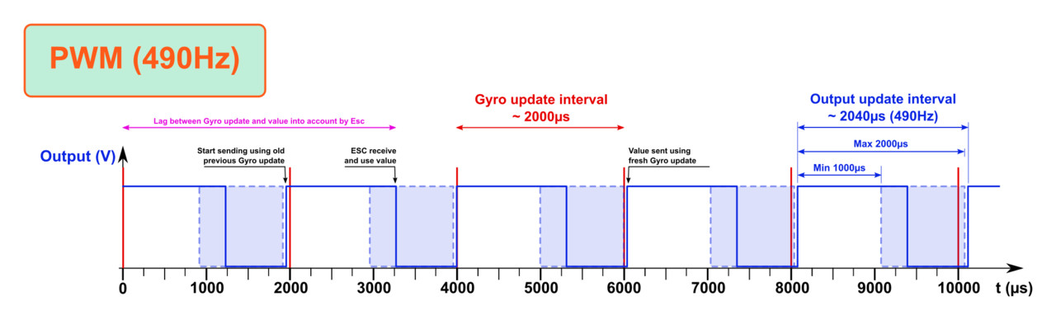
There are a variety of variations (for improved performance) on this scheme which are mainly determined by the ESC firmware and microcontroller. The firmware is the programming that implements all of the ESC functionality as accomplished by the microcontroller. It contains all of the different calculations that are required to interpret the input signal and control the motor. Sometimes it can be configured by the user for customization. The firmware is ultimately limited by the capabilities of the microcontroler. Microcontroller architectures have a wide variety of capabilities, and not all can support more exotic PWM schemes. The key is that the ESC needs to support the input signal scheme.
ESCs can also come with a variety of other options. They can have a variety of plugs for connections to a battery or to the motor. They can also have a battery elimination circuit (BEC), which can provide a steady voltage for other electrical components. Other improvements on the BEC are the SBEC and UBEC. These provide more power and reliability. ESCs without a version of the BEC are known as opto-ESCs. ESCs also have a voltage operation range, since the microcontroller and other electronics on the ESC are powered by a DC voltage regulator. This regulator can only upconvert or downconvert a certain range of voltages. Most ESCs are rated for use with 2S-6S LiPo batteries.
Part 2: Power Distribution Board
A quadcopter requires electric connections from the battery to multiple locations as well as electrical connections amongst various components (as pictured below).
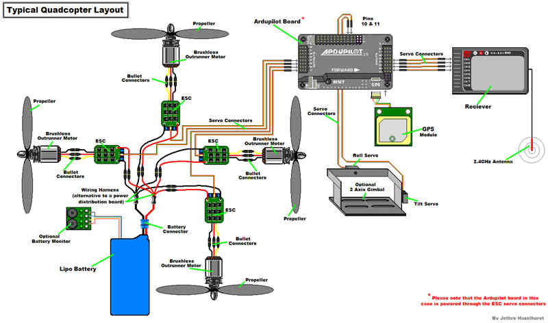 Source: Arducopter
The connections can be made using wires, but this has two disadvantages. First, the additional connectors and wires add extra mass to the UAV. Second, the wiring can interfere with both the electronics and the additional control wiring between components. A power distribution board (PDB) is probably the better approach. (Note that in the diagram above they use a wiring harness instead and the flight controller is actually powered through the ESC leads.) A PDB is essentially a printed circuit board, which is made of some insulating material like fiberglass that has copper (or another conductive metal) placed in cutouts on the surface and then covered such that only a few key points are exposed. These exposed areas are usually referred to as pads. At these points, you attach connectors or wires to the copper traces via soldering. You can buy a PDB stand-alone and mount it to a frame, probably with spacers, or you can buy a frame with an integrated PDB. More experienced users can even design and manufacture their own boards. Your choice of power distribution may also come with additional electronic components like a voltage monitor, current monitor, and voltage regulator for supplying a certain voltage level.
Part 3: Voltage Regulator/Power Monitoring Unit
A quadcopter's electronics will require a steady voltage level like 3.3V or 5V. The battery itself cannot meet these needs. Not only does the battery voltage decrease as the state of charge drops but the current draw from the motors can also make the voltage at the battery terminals sag (larger current through the internal resistance of the battery results in a larger voltage drop before the terminals). The solution is a voltage regulator. A regulator may possibly be called a power monitoring unit, linear regulator, switching regulator, or cascade regulator. Types of switching regulators are buck converters (steps down voltage only), boost converters (steps up voltage only), or buck/boost converters (steps voltage up or down) depending on the circuitry involved. Linear regulators are the least efficient, but are the cheapest. Switching regulators are the most common due to their lower losses in energy when converting between voltages. Sometimes, your design might require multiple regulators in order to supply the correct voltages. Some devices may have a regulator already built-in. Like with the ESCs, the available current supply is an important figure. If it is too close to the current required by the electronics, the regulator can have a decreased operational life or even fail with catastrophic results. A higher current rating results in increased mass and cost.
Part 4: Flight Controller
The flight controller is the heart of a UAV. It combines the user's input with sensory data to stabilize and move the UAV (among other things). The real need for a flight controller comes from the inadequacy of a human to easily control all of the flight characteristics. For instance, if the center of gravity for the UAV is not balanced, all the motors being set at the same speed would have the UAV fly off-canter. A good flight controller allows for an easier and enjoyable flying experience.
From a hardware standpoint, a flight controller generally consists of a microcontroller, integrated sensors, and input/output connectors. Addressing array of microcontrollers and associated software is beyond the scope of this guide. Suffice to say, the variation usually involves the processing capability and thus the number of available features. Most controllers include a gyroscope and accelerometer. The gyroscope senses the rotational motion of the UAV, and the accelerometer measures the three-dimensional forces exerted on the UAV. These allow for closed-loop feedback by the controller to optimize the motor output and account for changes in the center of gravity or the environment. Some models also allow for the integration of a GPS receiver and a magnetometer to let the controller know its position and heading.
Flight controllers have a variety of input and output signal connectors and schemes. The most basic is PWM, and this is almost a universal output for the ESCs. It can also be the input from the radio receiver. The main downside to this method is that each channel/parameter has to have a single connector. However, it is almost universally supported. PPM improves upon this by using more advanged analog techniques to reduce the number of cables needed. Analog signals, however, are more susceptible to external electronic interference. DSM and SBUS are digital varients that are also commonly used between the RX module and the FC. The FC can also connect to sensors using other digital protocols such as I2C, CAN, and UART. The important takeaway is that the FC needs to have both the software and hardware support for all of the other components you are including in your design.
We considered several flight controllers during our design of Eve. including the KISS FC, PIXHAWK, and DJI NAZA. We ultimately selected the DJI NAZA-M LITE. The NAZA-M LITE is capable of advanced flight modes but comes at a cheaper cost than the regular NAZA. It does not need extensive programming—it is configured using a simple GUI—and keep the cost of the quadcopter down while gaining important flight modes including return-to-home. Our purpose was to start with a reliable and easy to use platform. Future UAVs will most likely include a different FC that allows for more cutomization.
Part 5: Receiver and Transmitter
Very rarely does a UAV not have radio communications (even when flying autonomously). Essentially, you have to choose a module that will receive wireless commands from a base station or remote control. There are three important aspects to deciding on a RX module. First, you need to determine how many channels you need. Channels are essentially control inputs to the flight controller. The number generally ranges from 4-9. Second, you need to check if the RX outputs are compatible with the FC. RX modules usually have PWM/PPM outputs. (As a side note, you could control the ESCs directly from the RX module if need be.) Going with DSM or SBUS allows for more channels with just a single cable. Finally, the radio frequency that the RX module works on is important. The most common frequency is 2.4GHz. In general, this works well. However, it can be susceptible to interference in urban areas where WiFi is prevalent. Be aware that in the US, not all frequencies are legal to use even though you can buy the equipment. Lower frequencies allow for a longer range of communication at the cost of data bandwidth. For most amateur flights, range is not an issue, since the UAV has to be within sight.
The transmitter needs to match the RX module in both frequency and transmission protocol. Some brands are interoperable, but the safest choice is to have both be the same brand. Ergonomics for the controller only really apply if you plan on long flights. Considering that it is rarely beyond an hour or two, the controller features and reliability tend to be more important. These features can include multiple flight profiles for different UAVs, telemetry storage, external programming, transmit power, and number of channels.
Part 6: LED Indicators
A very important component of a quadcopter is LED indication. Having LEDs on the quadcopter can aid the pilot in knowing the orientation of the quadcopter as well as provide additional information on the state of quadcopter like its flight mode or whether or if the battery voltage is so low the quadcopter should land as soon as possible.