Step 5: Motor Selection
Now that we've selected an optimum propeller based on its ability to hover the quadcopter at the highest known available figure of merit, it is time to match that propeller to a motor.
Part 1: Brushed vs. Brushless DC Motors
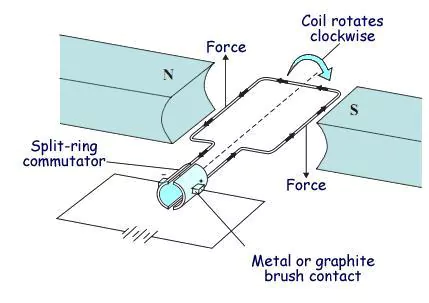
Let's start by developing how DC motors work. The two motors (both DC) often used in multirotor design are brushed DC motors and brushless DC motors. The brushed DC motor is likely the motor you learned about in high school or college physics class. Its operation is quite simple as shown in the figure below.
 Source: Mouser
A coil is subject to a magnetic field. When a voltage is applied to that coil, the coil experiences a a force causing it to rotate according to one of the many electrogmagnetic "right hand rules". This right hand rule is a handy way to visualize the cross product of a magnetic field vector and electric current vector resulting in a force. Put simply, when you move a charged particle through a magnetic field, it will experience a force equal to the cross product of the charge multiplied by its velocity vector crossed with the magnetic field intensity multiplied by its directional unit vector. If you are unfamiliar with the cross product, a trigonometric equation for this phenomenon is F = ILBsin(angle between length of wire and magnetic field direction). Now imagine you connect a voltage and the coil is subjected to a force per above. Eventually the current direction relative to the magnetic field vector will flip causing an increasing (remember that sine function!) opposing force. This reversal means the motor won't be able to continue spinning! To counteract this reversal, all you have to do is add a commutator. This device flips the polarity of the voltage across the coil so that the motor will always experience forces in the same direction. Watch the animation below to see this "flip" in polarity.
_80_degree_split_ring.gif) Source: Wikimedia
Source: Wikimedia
_80_degree_split_ring.gif)
The force (and thus the accerlation or speed) or the motor is increased by increasing the voltage. The relating equation for this relationship is defined as Angular Speed = Kv * V where Kv is a constant for that specific motor. Remember this constant because it will come up again.
You may be wondering what difference is between brushed and brushless DC motors by now. Well fundamentally, that commutator is an additional point of failure. Over time the brushes will wear out and the performance of the motor will suffer as a result. Enter Brushless DC Motors - BLDC for short. BLDC motors tend to be more expensive for multicopters but what you're paying for is a motor that tends to be more reliable and efficient over its brushed counterpart.
A BLDC motor trades out a commutator for electronic position control. This control is called PPM or Pulse Position Modulation. See the animation below.
 Source: Renesas
In a BLDC motor, the only moving part is the rotor. A controller applies voltage in sequence to a number of poles. Speed is again controlled by the magnitude of the applied voltage (so really there is pulse width modulation PWM enveloped here) but the rotation must be governed by PPM.
For our design, we thought it best to go with brushless motors. Brushed motors are only really worth it when you are trying to build a small, budget multirotor. If you are building a larger (more expensive) multirotor then we'd definitely advise using brushless motors.
Part 2: Torque Speed Curves
Now that we have discussed motor operation, let's move on to performance analysis. This is where we will develop a "working" understanding of motors in addition to the theoretical foundation we already laid.
Motors can be descriped using a graph called a torque speed curve. This is the most commonly desired piece of information for motors. A sample torque speed curve is shown below.
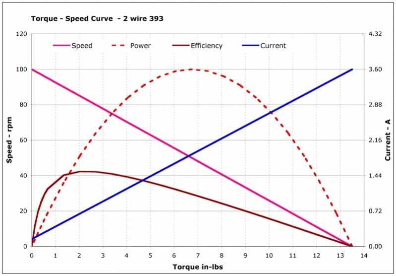 Source: JPearman
And another is shown here:
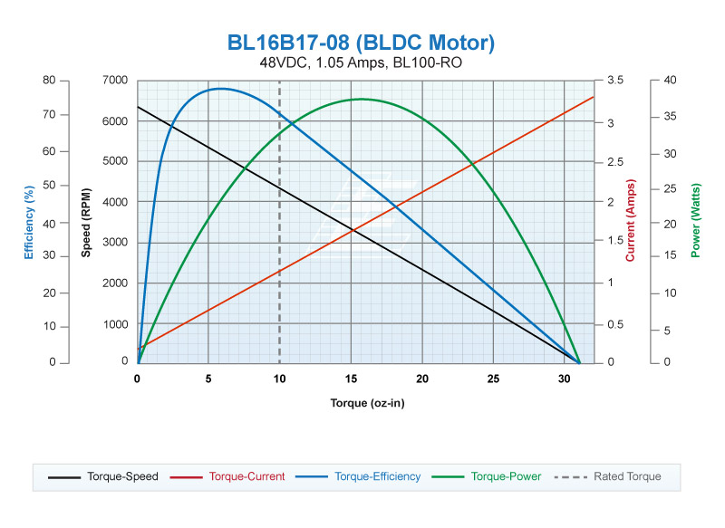 Source: Lin Motors
The first observation to make from a torque speed curve is that speed decreases as torque increases. Let's pretend you have a motor with no load on it. Then you apply a voltage to it. The corresponding speed is the no load speed and it is the fastest the motor with spin at that voltage. Now let's pretend we have added a load to the motor without changing the voltage. The motor will now spin at a slower speed. Now let's pretend we put a massive load on the motor that the motor actually cannot spin. The motor will exert a stall torque. (Remember balance of forces from the basics? The motor has a finite limit to how much torque it can produce before it stalls and will no longer turn. So the size of the load is inconsequential. The same load could stall a bigger or small motor too perhaps but at different torques!)
Next let's observe the power produced by a motor. We have earlier in this series defined this as mechanical power (as opposed to electrical or lifting power). The mechanical power produced by a motor is equal to the product of its torque and angular speed. On a torque speed curve, you will notice that this is visualized as the "area under the curve". Notice that the area under the curve will be greatest when the motor is running at half of its no load speed. If you really want to push the limits of motor power, this is where you want to be.
Next let's consider efficiency. A perfectly efficient motor would produce just as much mechanical power as the electric power it consumes. Notice that peak efficiency does NOT occur at peak power. Once the motor has reached peak efficiency, there is diminishing returns should you operate the motor to either side of it. This means that should you increase the mechanical power to reach peak power you will have to increase the electric power by more!
And finally let's consider the term we call the operating point. By operating point we mean the point on the torque speed curve that defines a motors performance. This is an important term to understand because different propellers will have different operating points when they hover quadcopters. The operating point will also change with a change in weight - perhaps if you add a payload - to the quadcopter. This brings us to matching a motor to a propeller.
Part 3: Matching a Propeller to a Motor
Let's consider the table for the APC 8x4.5MR propeller from the last section. Pretend that you want to hover a quadcopter with a mass of roughly 1.4kg. This requires each motor to lift roughly 350g. Referring to the table, we notice that a rotational speed of 7000rpm and mechanical power of 37.3W is required to hover. This gives us an operating point. Simply divide the power by the speed and you get the necessary torque.
Now that we have an operating point, we then need to research motors that can function at this operating point. This is perhaps the most difficult thing to wrestle with if you've spent time working with motors in the past actually. But we have a simple illustration to bring us all home.
First, make a plot area for a torque speed curve. Next, put a dot at the torque and speed of your operating point. Next, you need to draw a torque speed curve for a motor (or superimpose one) onto this plot area. Pick a voltage that gives a no load speed well above the operating point such that the point is below the curve. We will cover how to create a torque speed curve in the appendix at the bottom of this article rather than cover it here. Next, slide the line to the left until it touches the operating point dot. Divide the speed by the kv constant to get the operating voltage.
Finally, look at the corresponding point on the efficiency curve. This is the point of optimization for our quadcopter where we stressed flight time. Different motors will have different curves and the operating point will land at different places along those curves. You want to find a motor where the operating point is the closet to the operating point of peak efficiency. This is the ideal motor for a quadcopter that doesn't need fast response times and is looking to maximize flight time.
Now let's move past an illustration to a more computational model. We actually have another spreadsheet for performing motor calculations. We simply input the motor's parameters and the operating voltage, and then we get out data and graphs. We also added a feature where we can plug in our operating point to calculate the necessary voltage. Then we simply plug that voltage in to get the corresponding data and graphs specific to that operating point. See below!
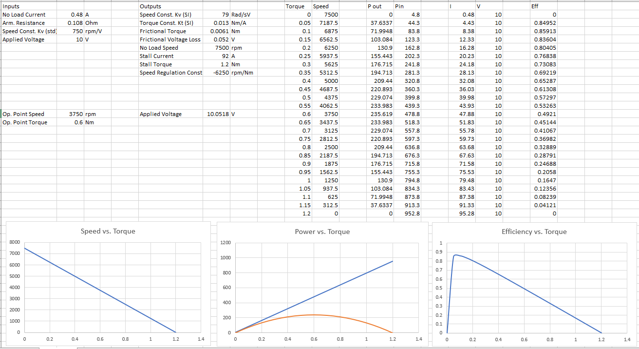
You can see in that snapshot how we put in a desired operating point and got a suggested 10.05V. For simplicity we just left the input voltage as 10V because we are limited here to two significant figures.
Motor Tables
Unfortunately, it is difficult to find torque speed curves (or the data necessary to compile them) for hobby motors. The best data you may obtain are thrust tables. The principle governing your analysis is the same. So it is a good idea to understand the previous section of this article.
Let's consider the T-motor MT-2216-11 motor available here. Here is a provided thrust table.
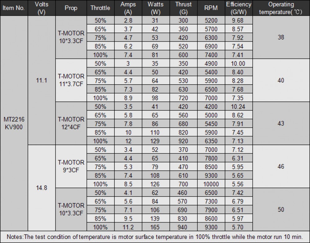
You can see it basically does some grunt work for you. You can assume a hover at a throttle of 50% or even 40% and look at the corresponding data based on battery voltage and propeller used. Note in particular max thrust. You should design your quadcopter to be capable of producing enough thrust to hover a quadcopter of twice the weight of what yours is. You need this buffer for climbing, manuevers, and flying in windy (but not too windy please!) conditions. Note also the efficiency given in grams per Watt. This definition of efficiency is also referred to as specific thrust and specific thrust is the better term that we will use from now on. Specific thrust is fairly common in multirotor design and it actually relates lifting thrust to electrical power. Unlike normal efficiency which always maxes out at 100%, specific thrust technically has an infinite limit. Basically as a propeller blade becomes infinitely long, the power necessary to achieve some specified amount of lift becomes infinitely small and thus the specific thrust becomes infinitely large. Specific thrust is very useful however when you consider a defined case. Let's consider the row for an APC 8x3.8SF propeller in the spreadsheet that calculates required rpm and lifting power that we showed earlier.
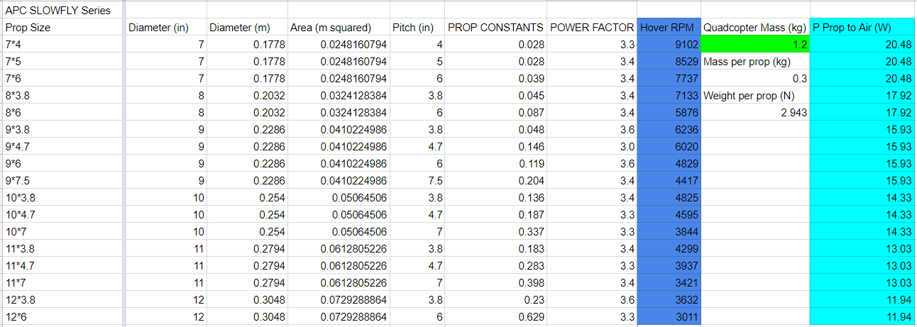
To get the ideal specific thrust for any propeller of an 8 inch diameter (remember the montemum theory derivation of power depends on diameter but not pitch and pitch came up later when calculating mechanical power) then we simply divide 300g by 17.9W and obtain an ideal specific thrust of 16.7 g/W. So obviously you want to get a specific thrust for an 8 inch propeller lifting 300g as close to 16.7 g/W as possible. If we consider the APC 12x3.8SF propeller then the ideal specific thrust would be 25.1 g/W and so on. Of course, you should compare the thrust tables as best you can against the calculations developed in earlier articles. If we adjust our spreadsheet to assume a mass per motor of 420g the ideal specific thrust drops to 21.2 g/W.

Now we can compare it to the T-motor table for the 12x4CF propeller. Notice that assuming a hover at 50% throttle the specific thrust is 10.24 g/W, roughly 48% of ideal. Further notice that rotational speeds are both shown to be 4200rpm! That's gratifying isn't it. Now how would we get from the 41W of electrical power to the 19.8W of lifting power? Let's assume a great motor efficiency of 80%. That leaves us with 32.8W of mechanical power. Dividing the lifting power by that mechanical power and you're left with an FoM of about 60%. That's a very reasonable value for FoM!
And here we will point out a cruel part of the world we live in. The thrust data is based on using not only certain propellers, but T-motor carbon fiber propellers. We advise being wary of such specificity. We don't have anything against T-motor, but their carbon fiber propellers are simply not worth our buying for our quadcopter design because we are trying to push flight performance with a heavy restriction on budget. Perhaps they will be suitable for your quadcopter build though! Anyway, the thrust data must be taken with a grain of salt because the performance of different propellers can vary greatly from prop to prop. We won't get into Reynolds numbers here. If you look up Brad Hughey's work here that you may find satisfactory info on this.
While we may really like to know the motor efficiency of the T-motor above, we simply cannot without having the necessary data on the propellers in question to know derive their FoM. Most likely the motor efficiency was below 80% and the propeller FoM was about 60% though.
Now let's find another motor similar to the one above with thrust tables provided. The Emax MT2213 that can be found here looks pretty similar. Here's the provided thrust table.
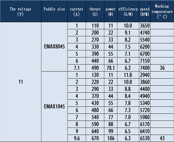
Notice that to hover a mass of 420g per motor the Emax set up with the specified propellers has a lower specific thrust than the T-motor setup by roughly 25%! Quadcopter design is a game of inches as it were. A 25% decrease in specific thrust is a 25% decrease in hover time! We have now developed in detail a case for serious, thorough quadcopter design. Two quadcopters with similar weight and motors and propellers could have drastically different flight times.
Conclusion
Once you have have selected a propeller for your quadcopter with the highest FoM you can find at hover, you must next select a motor that has the highest efficiency you can find for that operating point. Another way to say this is that you need to optimze the specific thrust of your quadcopter motors. Just remember that a "good" value for specific thrust is relative because ideal specific thrust varies with both quadcopter mass and propeller diameter. The key to optimization based on specific thrust is get the highest specific thrust you can for your given quadcopter mass. Adjust the propeller and motor selection as necessary to do so.
Appendix
Here we will develop the concept of a torque speed curve more thoroughly. Let's consider a pretty basic motor that you can by from Hobby King here. The listed Kv of this motor is 750 rpm/V. It is rated for 3S-4S batteries (7.4V to 11.1V). It has a no load current of .48A when 10V is applied. It has an internal resistance of .108 Ohms. The max power (incorrectly labeled as current) is 350W. And the max current is 21.5 Amps.
Next we will lay out some equations to consider.
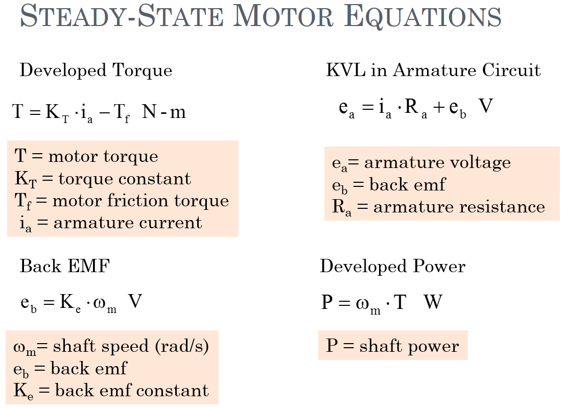 Source: SIU
Now let's start building a torque speed curve. We will start with with the no load current and internal resistance. If you apply 10V across the motor with no load you will get .48A through a resistance of .108 Ohms. The voltage drop across that resistance will then be .052 Volts. This leaves a back emf of 9.95V which we will then multiply by the speed constant Kv to obtain a no load speed of 7460 rpm.
Now that we have the no load speed and the stalled speed (which is of course zero) we will calculate the associated torque values. To do this we need to derive the torque constant Kt (in SI units this the units are Nm/A). In SI units Kt is equal to the inverse of Kv where Kv is defined as rotational speed divided by back emf as it is for this motor. If you find a motor with Kv given in back emf divided by rotational speed with SI units then Kt will equal Kv. First we will convert rpm to radians per second by dividing by 60 and multiplying by 2pi. Kv now is equal to 79 (rad/s)/V. Now we will simply invert this number to attain Kt. Kt is then equal to 1.3 x 10^(-2) Nm/A.
Next we will calculate the stalled current to get the stalled torque. We know at a stall the motor is not moving and there is therefore no back emf. This means that all 10V will be across the internal resistance. The stall current Ist then is then given by 10V/.108Ohm - Tf = 92A. We will pause and say that of course you do not want to stall your motor and achieve this level of current. Stalling can easily damage a motor. Now we can calculate Tst by multiplying 92A by Kt and then subtracting the resistive frictional torque. Tst = .013 Nm/A x 92A - Tf = 1.2Nm - .013 Nm/A x .48A = 1.2 Nm (the value doesn't reduce at 2 sig figs) This equation can be reduced as follows. Tst = .013 Nm/A x (92A - .48A)
Now that we have the two extreme operating points, we can draw our torque speed curve.
Now you may have a question in your mind. "Is there any torque being produce by the motor at no load?" This is a good question because there is current. If we multiply Kt by the no load current we get the following torque. Tnl = .013 Nm/A x .48A = 6.1 x 10^(-3) Nm But this is not torque as we typically think of it. This torque is not available to turn a load. It is actually the torque required to counteract the resistive torque of friction we calculated earlier! Furthermore, this is roughly a set a value because kinetic friction does not vary with speed. (Though there are at least 4 friction models to consider when performing a detailed frictional analysis of a motor. This set value will suffice though.) So no matter what voltage you apply, you will lose roughly .052V in the steady state across the motor resistance to counteract resistive torque due to friction. We state that this applies to the steady state because this is not the case at start up. At start up, you have to apply a voltage to produce a current to overcame torque due to STATIC friction. Static friction is stronger than kinetic friction. So if you were to look at a graph of the current with respect to time of a motor starting and then settling into steady state operation, you may see the current spike and then settle down.
References: Motor Torque Constant section here Page 392 here Buhler